Org. Synth. 2024, 101, 342-365
DOI: 10.15227/orgsyn.101.0342
Preparation of Highly Reactive Lithium Metal Dendrites and the Synthesis of (Trimethylsilyl)methyllithium
Submitted by Raquel M. Gonzalez, Han-Hsiang Hsu, and Andy A. Thomas*
Checked by Bilal Altundas and Scott E. Denmark
1. Procedure (Note 1)
A. Highly Activated lithium Metal Dendrites (1). An oven-dried (Note 2) 24/40, 1 L, three-necked, round-bottom flask (Note 3) was equipped with a cylindrical glass-coated magnetic stirring bar (1/2 inch x 3/8 inch, length x diameter) and fitted with a dry ice condenser (Note 4), an argon inlet, and a vacuum adapter incorporating a PTFE flow control valve set to the closed position (Figure 1) (Note 5). The top dry ice condenser hose outlet was connected to the Schlenk manifold via rubber tubing. The bottom hose outlet was connected to rubber tubing attached to a flow control valve set to the closed position (Note 6). The system was evacuated under vacuum (50 mTorr) and backfilled with argon three times (Note 7) and maintained under a positive pressure of argon.
To a 24/40 necked, 100-mL, flame dried Schlenk flask stoppered with a rubber septum and equipped with an egg-shaped magnetic stirring bar (3/4 inch x 3/8 inch, length x diameter) was added high-sodium lithium pellets (5.0 g, 0.72 mol) (Note 8) under a positive pressure of argon at 21 °C (Figure 2a). Dry hexanes (20 mL) (Note 9) were added through the rubber septum with a 60 mL syringe equipped with a 10 inch 20-gauge, stainless steel needle and the mixture stirred for 5 minutes (Figure 2b and 2c). Then, the stirring was stopped and the hexanes were removed using another syringe equipped with the same type of needle (Note 10). This process was repeated an additional two more times after which the lithium pellets were placed under hi-vacuum (50 mTorr) at 21 °C for 1 h to remove any residual hexanes (Figure 2d). Then, the flask was placed while maintaining a positive pressure of argon and the lithium pellets transferred to the three-necked, 1 L flask under a positive pressure of argon. After reconnecting the dry ice condenser, the assembled glassware was evacuated under vacuum (50 mTorr) and backfilled with argon three times, then maintained under a positive pressure of argon.
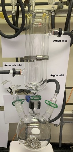
Figure 1. Dry ice condenser and three necked flask containing lithium pellets. (photo provided by checkers)
Figure 2. (a) Schlenk flask containing lithium pellets (b) rinsing with hexanes (c) stirring with hexanes (d) drying pellets under vacuum (photos provided by checkers)
A separate flame-dried, 24/40, 250-mL, 2-necked flask was stoppered with a flow control valve connected with rubber tubing leading to the Schlenk manifold and a 24/40 glass vacuum adapter attached to rubber tubing leading to the ammonia tank (Figure 3a). The flow control valve was set to the closed position, the tubing was removed and replaced with tubing leading to a separate bubbler (Figure 3b). The flask was submerged into a liquid nitrogen bath and the ammonia tank was opened to allow for a steady flow of ammonia. Once 150 mL of liquid ammonia was condensed (Figure 3c and 3d), the ammonia tank was closed and the flow control valve leading to the bubbler was set to the closed position (Note 11 and 12). The tubing leading to the bubbler was removed and replaced with Teflon tubing equipped with a one-way check valve attached on the other end to the dry ice condenser after removing the large 24/40 rubber septum (Figure 4) (Note 13). Dry ice and acetone was added to the top of the condenser and the 3-necked flask containing the lithium pellets was submerged into an external acetone-dry ice bath (Figure 5) and the reaction system was set to stir at 200 rpm.
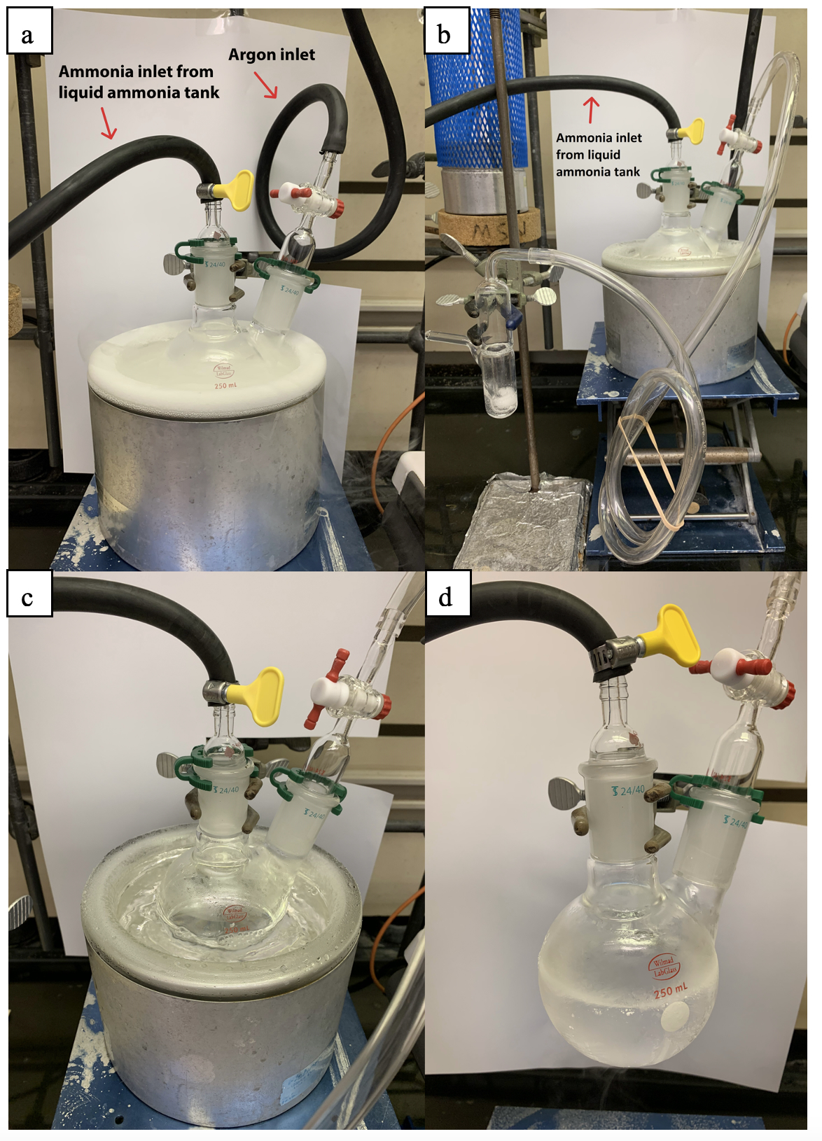
Figure 3. Ammonia condensation assembly: (a) Ammonia collection flask submerged in liquid nitrogen; (b) Flask connected to a bubbler and ammonia condensation began; (c) condensed ammonia in liquid nitrogen; (d) 150 mL liquid ammonia removed from liquid nitrogen bath.
Figure 4. Ammonia transfer setup from round bottom flask to the dry ice condenser (photo provided by checkers)
Figure 5. Reaction flask submerged in dry ice-acetone bath prior to ammonia transfer.
After being submerged for 10 minutes, the flow control valve equipped to the 250 mL flask containing liquid ammonia was opened and the ammonia transferred to the 3-necked flask to dissolve the lithium metal (Figure 6a).
Figure 6. Reaction setup for lithium dendrite formation: (a) beginning of ammonia condensation (photo provided by checkers); (b) After the completion of ammonia addition and 15 minutes of stirring (c) prior to removal of dry ice condenser wrapped in paper towels; (d) flask immediately after removal of dry ice bath.
Once all of the ammonia was condensed, the flow control valve was closed and the lithium-ammonia solution was allowed to stir at -78 °C for 15 min to give a blue-bronze-colored solution (Note 14) (Figure 6b). The dry ice condenser was carefully removed (Note 15) (Figure 6c) under a positive pressure of argon and interchanged to a glass penny head stopper. Thereafter, the flask is removed from the -78 °C bath (Figure 6d) and allowed to stir at room temperature for 30 minutes where the ammonia boils slowly (Figure 7).
Figure 7. Bronze-colored solution of lithium in ammonia. (photo provided by the checkers)
After 30 minutes, the boiling of the ammonia slowed down. The 3-necked flask was submerged into a 40 °C oil bath to aid the evaporation of the residual ammonia. The system was then subjected to vacuum (50 mTorr) with a secondary liquid N2 trap (Figure 8 and 9) (Note 16). After the evaporation of all liquids, the secondary trap was removed, and the flask was directly connected to vacuum for an additional 12 hours in an external oil bath set to 21 °C to yield lithium-dendrites (1) with a gray metallic color (Figure 10) (Note 17).
Figure 8. Secondary liquid N2 trap (photo provided by the checkers)
Figure 9. Reaction connected to the secondary liquid N2 trap. (photo provided by the checkers)
Figure 10. Lithium dendrites: (a) prior to vacuum; (b) after 12 h under vacuum (photos provided by submitters)
B. (Trimethylsilyl)methyllithium (3). The reaction flask containing lithium-dendrites was refilled with argon and submerged into an oil bath set to 37 °C. With a positive pressure of argon, the glass penny head stopper was briefly removed, and the lithium-dendrites were gently scraped down the walls to the bottom of the flask using an oven-dried spatula (Note 18). The glass penny head stopper was then reattached (Figure 11).
Figure 11. Li-dendrites scraped down. (photo provided by the checkers)
The reaction vessel was fitted with an oven-dried reflux condenser connected to an argon inlet, a 500-mL pressure-equalizing addition funnel fitted with a rubber septum, and a vacuum adapter incorporating a PTFE flow control valve set to the closed position (Figure 12). The system was evacuated under vacuum and backfilled with argon three times and maintained under positive pressure of argon. Then 160 mL of dry pentane (Note 19) was added to the three-neck flask through the addition funnel, and the valve of the addition funnel was closed. The reaction vessel was stirred, and the condenser was connected to water inlet and outlet tubing that were secured with hose clamps.
(Trimethylsilyl)methyl chloride (2) (34.6 g, 0.282 mol, 1.0 equiv) (Note 20) was weighed in a separate, argon-purged 100 mL Schlenk flask, and rinsed into the addition funnel with 120 mL dry pentane. The solution in the addition funnel was mixed by gently agitating the system, then the valve was adjusted to a drop rate of ca 1 drop per second to maintain a gentle reflux of pentane, where the reaction material slowly turns into a dark heterogeneous mixture. Upon the end of the addition of 2, the addition funnel was rinsed with an additional 20 mL dry pentane then replaced with a 24/40 rubber septum. The gray-purple heterogeneous solution was maintained under reflux for ca 3 h - until 2 was consumed as monitored by GC-FID (Note 21).
Figure 12. Addition funnel and reflux condenser (photo provided by checkers)
Upon full consumption of 2, a 200-mL air-free Schlenk filtration funnel equipped with a coarse porosity glass fritted disc was charged with deactivated celite (ca 3 cm pad) (Note 22) and attached to the top of an oven-dried pre-weighed 1 L 2-necked round bottom flask with the other neck fitted with a flow control adapter set to the closed position (Note 23). The system was evacuated under vacuum (50 mTorr) and backfilled with argon three times and maintained under a positive pressure of argon (Figure 13a). A Tygon tubing line (ca 3 feet) leading to an oil bubbler was connected to the flow control adapter to allow pressure equilibrium during cannulation and filtration. Oven-dried (70 °C) PTFE tubing (Figure 14) fitted on a rubber septum at each end (Note 24 and 25) was attached to the top of the filtration funnel to allow argon to purge the tubing for 1 min. The other side of the PTFE tubing was then fitted to the three-neck flask (Figure 13b), and the position of the tubing was adjusted to be under the liquid surface. The argon inlet of the filtration funnel was closed to initiate the cannulation of reaction mixture into the filtration funnel. After complete transfer of solution, the reaction flask was rinsed with an additional 30 mL of dry pentane and the remaining solution was cannulated into the filtration funnel.
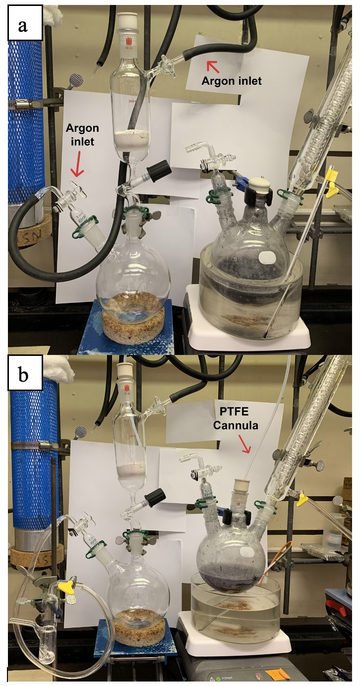
Figure 13. Filtration funnel setup. (a) Evacuation and backfill of filtration apparatus with vacuum/argon; (b) Insertion of cannula and beginning of filtration (photos provided by the checkers)
Figure 14. PTFE tubing fitted to rubber septa (photo provided by the submitters)
After completion of the cannulation, the flow control valve was set to the closed position and the tubing and bubbler was removed. An argon line was attached to the flow control valve which was then turned to the open position to fill the receiving flask with a positive pressure of argon. The filtration funnel was then quickly removed and the receiving flask was fitted with a rubber septum. The resulting clear solution was then transferred to an oven dried pre-weighed 500 mL Schlenk flask (Note 23). A portion of the solution was withdrawn for density measurement (Note 26) and the concentration of the organolithium reagent was determined by a modified Gilman titration (Note 27). From the concentration, density, and the weight of the solution, the yield was calculated to be 68.6% (0.98 M, 196 mL) A subsequent run provided higher yields (80%) in agreement with the submitted procedure (Note 29, Note 30) (Figure 15).
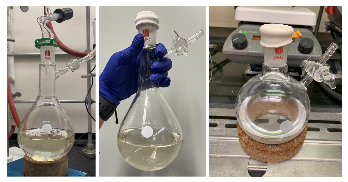
Figure 15. (Trimethylsilyl)methyllithium (left and middle, photo provided by submitters) (right, photo provided by checkers)
2. Notes
1. Prior to performing each reaction, a thorough hazard analysis and risk assessment should be carried out with regard to each chemical substance and experimental operation on the scale planned and in the context of the laboratory where the procedures will be carried out. Guidelines for carrying out risk assessments and for analyzing the hazards associated with chemicals can be found in references such as Chapter 4 of "Prudent Practices in the Laboratory" (The National Academies Press, Washington, D.C., 2011; the full text can be accessed free of charge at
https://www.nap.edu/catalog/12654/prudent-practices-in-the-laboratory-handling-and-management-of-chemical. See also "Identifying and Evaluating Hazards in Research Laboratories" (American Chemical Society, 2015) which is available via the associated website "Hazard Assessment in Research Laboratories" at
https://www.acs.org/about/governance/committees/chemical-safety.html. In the case of this procedure, the risk assessment should include (but not necessarily be limited to) an evaluation of the potential hazards associated with
lithium,
ammonia,
(trimethylsilyl)methylchloride,
1,2-dibromoethane,
pentane,
(trimethylsilyl)methyllithium, as well as the proper procedure for handling of
lithium metal and
ammonia.
Ammonia should be operated in a well-ventilated fume hood. A class D fire extinguisher should be available throughout the procedure.
2. All glassware was placed in a 150 °C oven overnight prior to use unless otherwise noted.
3. To measure the volume of
ammonia needed, 150 mL of water was measured into the 1 L reaction flask and a secondary, 250-mL
ammonia collection flask. The liquid level was marked with a marker prior to oven drying. Before the reaction, the liquid level was marked again with electrical tape to prevent
acetone from removing the marker.
4. Dry ice condenser specifications: Ace Glass Part No. 8757-35 with the following specifications: 24/40 bottom, 50 x 250mm cold finger, #15 Ace-Thred
TM inlet/outlet complete with Ace-Safe
TM connectors for 1/4in ID tubing.
5. Glindemann PTFE sealing rings (Sigma-Aldrich SKU Z502316-1PAK) were added to attachments that are directly attached to all glassware.
6. The submitters used a 14/20 rubber septum to cover the dry ice condenser outlet. The checkers connected the bottom tubing outlet to a rubber tubing leading to a flow control adapter set to the closed position attached to the flask used for collecting condensed
ammonia.
7.
Argon gas was supplied by Airgas and was passed through a drying tube packed with Drierite Indicating 8 Mesh 1# (Blue) (7778-18-9). The vacuum pressure was measured to be 100 mTorr and was equipped with a liquid-
N2 trap.
8. High-Sodium
Lithium pellets were supplied by Millipore-Sigma (cat# 444456-50G).
9. Hexanes were dried by percolation through two columns packed with neutral alumina under a positive pressure of
argon from a solvent purification system.
10. The hexanes washes were collected in an oven-dried Erlenmeyer flask, cooled to 0 °C in an ice bath and quenched with
isopropanol (5 mL) and
methanol (5 mL). The resulting solution was disposed of as organic waste.
11.
Ammonia, anhydrous, was supplied by MG Industries Gas Products.
12. The checkers condensed
ammonia as a gas into a secondary 250 mL flask immersed in a liquid
nitrogen bath and the collection continued until 150 mL of
ammonia was obtained. The
ammonia was then allowed to evaporate and condense into the reaction flask. The submitters note that adding
ammonia as a liquid
via eductor tubes may introduce trace impurities such as iron salts and its impact on the formation of Li-dendrites is unknown. The submitters condensed
ammonia as a gas directly onto the dry ice condenser.
13. A one-way check valve was connected to the tubing leading to the dry ice condenser to avoid back pressure when condensing
ammonia.
14. The reaction flask remains in the -78 °C bath until all
lithium is fully dissolved and no remaining
lithium pellets were observed.
15. The dry ice condenser was wrapped with a towel to prevent water condensation from entering the reaction flask while removing the dry ice condenser.
16. As a secondary liquid
nitrogen trap the submitters used the following: a three neck 1 L flask was fitted with a vacuum outlet, a glass penny head stopper, and a gas adaptor. The flask was connected to the reaction vessel evacuated to vacuum with the metering valve closed before being submerged to an external liquid-
N2 bath, and the metering valve was opened to reaction vessel when needed. The checkers used a 24/40, 250 mL, 2-necked flask equipped with a glass flow control adapter attached to the vacuum line and a glass adapter. The glass flow control adapter was opened to the reaction vessel as needed.
17. The
ammonia in the secondary trap was allowed to evaporate in the ventilated fume hood overnight.
18. While scraping dendrites with a dry metal spatula, positive
argon pressure should be maintained. The checkers quenched the spatula after use by rinsing with
isopropanol (5 mL) and
methanol (5 mL). The waste solvent was then disposed of as organic waste. Alternatively, the submitters reported quenching the spatula directly in ice.
19. Dry
pentane (HPLC grade) was dried over sodium rods and distilled.
20.
(Trimethylsilyl)methyl chloride was supplied by Oakwood Chemicals and distilled over
calcium hydride from Thermo Scientific (Catalog No. 019106.22). The checkers provide the following protocol for drying: A flame dried 14/20, 250 mL, 3-necked round bottom flask equipped with an egg-shaped stir bar (3/8 inch x 3/16 inch, length x width) and fitted with a penny head stopper (right neck), an
argon inlet adapter (left neck) and a rubber septum (middle neck).
CaH2 (10 g) followed by
(Trimethylsilyl)methyl chloride (100 mL) was added under a positive pressure of
argon by removal of the penny head stopper. Once all the materials were added, the penny head stopper was placed back into the neck, the rubber septum removed from the middle neck and an oven dried solvent distillation head equipped with a built-in reflux condenser was attached. The
argon inlet was quickly replaced with a penny head stopper and the
argon inlet attached to the top of the distillation head (Figure 16a). The assembled apparatus was lowered into an oil bath and heated to 130 °C (oil bath external temperature) (Figure 16b).
Figure 16. (Trimethylsilyl)methylchloride distillation apparatus (photos provided by the checkers)
21. The submitters report the following protocol for GC monitoring: A 50-µL sample of the reaction is transferred
via 1 mL a plastic syringe into a vial filled halfway with 2 mL DI water. Hexane was added to extract the mixture. The layers were allowed to separate, and the top organic layer was passed through a filter pipette with cotton and sodium sulfate into a sampler vial. This is repeated ca. every 30 minutes until full consumption of starting material. Gas Chromatography (GC) spectra were recorded on an Agilent 8860 GC System equipped with J&W DB-5 TA dioxin column (60 m x 0.32 mm, P/N G3903-63006), using a flame ionization detector (FID). The standard method for reaction monitoring holds a temperature of 50 °C for 2 min and ramps up (10 °C/min) to a final temperature of 150 °C which is held for 1 min. The retention time of
2 was found to be 4.6 min. A similar protocol was followed by the checkers however diethyl ether was used as the extraction solvent and the reaction checked every hour until full consumption (3 h) was observed. The Gas Chromatography (GC) spectra were recorded on a Shimadzu GC-2010 Plus Gas Chromatograph equipped with an SH-Rxi-5ms column (15 m x 0.25 mm, Restek Catalog No. 13420), using a flame ionization detector (FID). The standard method for reaction monitoring holds a temperature of 30 °C for 2 min and ramps up (10 °C/min) to a final temperature of 150 °C which is held for 2 min. The retention time of
2 was found to be 1.54 min. Completion of the reaction was ascertained by complete disappearance of the peak for
2.
22. Celite was supplied by Thermo Fisher Scientific (Filter aid, Celite Hyflo Supercel
®, Catalog No. B22658.36) and prepared by an acid wash protocol as follows: 100 g of Celite was weighed into a 1 L Erlenmeyer flask equipped with a cylindrical magnetic stirring bar (1.5 inch x 5/16 inch, length x width). 600 mL of 6 M aqueous HCl was added slowly to the Erlenmeyer flask, and the mixture was stirred overnight. The next day, the mixture was filtered with a 2 L fritted Buchner funnel of coarse porosity under reduced pressure (300 Torr). The Celite was washed with deionized water until the filtrate tested neutral (pH = 7), then rinsed with
methanol (150 mL) and deionized water (150 mL) subsequently. The excess water was filtered under reduced pressure (300 Torr), and the resulting Celite was dried in a vacuum oven at 150 °C, 5 Torr for 12 h. Alternatively, the submitters report that the washed Celite can be dried in an oven at 150 °C, ambient pressure for at least 5 days then transferred to a glovebox or the filtration setup, purging with
Argon prior to use.
23. The checkers used a 2-necked 1 L round bottom flask due to availability and transferred the solution to an oven dried pre-weighed 500 mL Schlenk flask via an oven dried stainless steel 18-gauge, 12-inch cannula. In both runs, some precipitation of an off-white solid was observed in the receiving flask after filtration. The checkers obtained a clear, colorless organolithium solution. Alternatively, the submitters directly filtered the organolithium solution into an oven dried, pre-weighed 1 L Schlenk flask (Figure 17) and after completion of the cannulation, the bubbler was removed, and the receiving flask was reattached to an
argon inlet with positive pressure. The filtration funnel was then briefly removed, and the receiving flask was fitted with a rubber septum. The submitters then weighed the resulting light-yellow solution.
Figure 17. Filtration setup (photo provided by submitters)
24. The submitters report using the following PTFE tubing setup: Two large rubber septa were penetrated in the center and connected by 1 m PTFE tubing (Restek P/N #27846 1/8 inch o.d., 0.094 inch i.d.). In the checkers hands, this internal diameter tubing caused significant clogging during the cannula transfer. This resulted in incomplete transfer of the organolithium solution and a lower yield than reported by the submitters. In the second run, the checkers used larger diameter PTFE tubing (Grainger Parker Item No. 53XL54, 3/16 o.d, 1/8 inch i.d) connected similarly to two large rubber septa (Suba-Seal spectra, Sigma Aldrich, Catalog No. Z167320). The larger diameter alleviated the clogging issue and allowed for complete transfer of the organolithium solution.
25. The ends of the tubing were cut at a 45° angle to create a bevel shape for easier penetration of the septa.
26. Density was calculated by measuring a 500-µL sample of organolithium reagent in an oven-dried dram vial according to the following formula:
27. Modified Gilman Titration: An oven-dried, 10-mL round-bottom flask and a 50-mL, round-bottom flask, were each equipped with a Teflon-coated egg-shaped magnetic stir bar (3/8 inches x 3/16 inches, length x width) and fitted with a rubber septum. The 10-mL flask was charged with
1,2-dibromoethane (200 µL) (
Note 28) and dry
THF (3 mL, dried by percolation through two columns packed with neutral alumina under a positive pressure of
argon); and the 50-mL flask was charged with 20 mL degassed water (HPLC grade). 500 µL (V
RLi) of the organolithium reagent was added to both flasks. After the completion of the addition, the septa were removed and water (1 mL, HPLC grade) and phenolphthalein indicator (1 wt% solution in 1:1
H2O/
isopropanol, 2 drops) were added to each flask. The resulting solutions were each titrated with aqueous HCl (0.23 M)
via a 500-µL Hamilton syringe, and the endpoint volumes were recorded as V
residual base (from 10-mL flask) and V
total base (from-50 mL flask). The concentration of the active organolithium reagent (C
RLi) was given by the following equation:
28.
1,2-dibromoethane was supplied by Thermo Fisher Scientific and was used without purification.
29. The checkers found that the initial run with the similar dimension PTFE cannula used by the submitters caused issues in fully transferring the organolithium solution to the inert filtration apparatus due to clogging of the tubing. A second run utilizing a wider internal diameter PTFE tubing for cannula transfer allowed for efficient cannulation. Upon utilizing the wider internal diameter tubing (see
Note 24), yields similar to those originally reported by the submitters were obtained. In the checkers hands, the second run of the reaction on the same scale gave the following results: 0.98 M, 230 mL, 79.8%. The submitters report their second run as follows: 0.86 M, 270 mL, 80.3%.
30. Quenching of the residual
lithium dendrites should be approached with care as they are highly reactive. The submitters report quenching the
lithium dendrites as follows: While maintaining the flow of
argon into the reaction flask, the residual
lithium metal (usually as blue/gray powder after the reaction) was quenched using a long spatula to place small portions of metal onto large amounts of ice in a 19-L plastic bucket. The filter cake on celite was quenched in a similar manner. The checkers suggest the following as an alternate protocol that is safer and avoids spontaneous reaction of
lithium with ice. The filter cake is carefully transferred under a positive pressure of
argon to the 3-necked 1 L flask containing the residual
lithium dendrites via inverting the filtering apparatus into a glass funnel attached to one of the necks of the 1 L flask. The funnel is removed, a large egg-shaped stir bar (1.5 inches x 0.625 inches, length x width) is added, and the 1 L flask stoppered with a rubber septum, an
argon inlet and an addition funnel. The assembled system is then submerged into an ice bath, the addition funnel is filled with 300 mL of Xylenes (ACS grade), stoppered with a rubber septum and the xylenes added to the flask at a rate of ca 10 mL per minute. Upon complete xylenes addition, the contents of the flask are stirred at 130 rpm and the addition funnel is filled with 300 mL of
isopropanol (ACS grade). The addition funnel stopcock is slowly opened to allow for a rate of ca 1 drop per second and the quenching process monitored accordingly. Upon complete addition, a transparent slurry containing no observable
lithium metal is obtained. An additional 100 mL of
MeOH (ACS grade) is added to the addition funnel and slowly added to the 1 L flask to ensure that the
lithium metal is completely quenched. The resulting solution is then disposed of as organic waste.
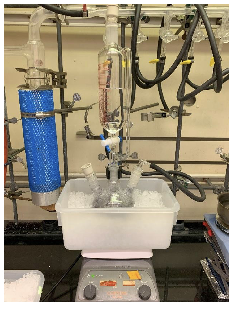
Figure 18. Lithium dendrite quenching setup (photo provided by the checkers)
Working with Hazardous Chemicals
The procedures in
Organic Syntheses are intended for use only by persons with proper training in experimental organic chemistry. All hazardous materials should be handled using the standard procedures for work with chemicals described in references such as "Prudent Practices in the Laboratory" (The National Academies Press, Washington, D.C., 2011; the full text can be accessed free of charge at
http://www.nap.edu/catalog.php?record_id=12654). All chemical waste should be disposed of in accordance with local regulations. For general guidelines for the management of chemical waste, see Chapter 8 of Prudent Practices.
In some articles in Organic Syntheses, chemical-specific hazards are highlighted in red "Caution Notes" within a procedure. It is important to recognize that the absence of a caution note does not imply that no significant hazards are associated with the chemicals involved in that procedure. Prior to performing a reaction, a thorough risk assessment should be carried out that includes a review of the potential hazards associated with each chemical and experimental operation on the scale that is planned for the procedure. Guidelines for carrying out a risk assessment and for analyzing the hazards associated with chemicals can be found in Chapter 4 of Prudent Practices.
The procedures described in Organic Syntheses are provided as published and are conducted at one's own risk. Organic Syntheses, Inc., its Editors, and its Board of Directors do not warrant or guarantee the safety of individuals using these procedures and hereby disclaim any liability for any injuries or damages claimed to have resulted from or related in any way to the procedures herein.
3. Discussion
In the preparation of organolithium reagents, the use of highly activated lithium metal surfaces is essential. Currently, commercially available sources provide high surface area lithium in the form of powders or dispersions. Our group has presented a new approach to synthesize lithium with clean and high surface areas up to 100 times greater than conventional Li-dispersion. Our method involves the use of liquid ammonia (NH3) to effectively clean the lithium surface, resulting in the controlled dendritic growth of lithium structures along the flask wall. This freshly synthesized and highly activated lithium exhibits consistency and reliability, enabling the scalable production of organolithium reagents, ranging from 0.1 mmol to 0.5 mole. Herein, we outline the procedure for applying 5 grams of Li-dendrites in the synthesis of (trimethylsilyl)methylchloride, highlighting the potential impact of our method on organometallic chemistry.
Appendix
Chemical Abstracts Nomenclature (Registry Number)
Lithium: granular, 4-10 mesh particle size, high sodium, 99% metal basis 4 (1) (7439-93-2)
Celite (68855-54-9)
(Trimethylsilyl)methylchloride (2344-80-1)
1,2-dibromoethane (106-93-4)

|
Raquel M. Gonzalez was born in Sacramento, CA and later moved to College Park, MD. In 2018, she worked under the tutelage of Prof. Eugene Mazzola from the University of Maryland, in collaboration with the FDA, to study the dye Red 33. She is an undergraduate at Texas A & M University and began research with Prof. Andy A. Thomas during her freshman year, Spring 2023. Her research focuses on the synthesis of organolithium reagents using highly activated lithium metal dendrites and the development of new tools for new synthetic methods. Outside of the lab, Raquel enjoys advocating for DEI efforts in STEM, baking new recipes, and listening to 90s hip-hop.
|

|
Han-Hsiang Hsu is from Hsinchu, Taiwan. He received his B.S. in Chemistry at National Taiwan University in 2021, where he worked on transition metal-catalyzed cross-coupling reactions under the supervision of Professor Shiuh-Tzung Liu. He joined the Thomas Group in 2021 and is currently a Ph.D. candidate. His main research focus is on the selective functionalization of heterocyclic molecules.
|

|
Andy A. Thomas received both his B.S. and M.S. degrees in chemistry from UNCC. In 2011 he moved to UIUC to begin his Ph.D. with Prof. Scott Denmark. Upon completion of his Ph.D. in 2017 he began his NIH postdoctoral fellowship at MIT with Prof. Stephen Buchwald. In the Fall of 2020 Andy joined the chemistry faculty at Texas A&M University. His research group focuses on using physical organic chemistry to develop new synthetic methods by investigating the chemical reactivity of highly reactive intermediates.
|
|
Bilal Altundas received his B.S from Middle East Technical University in Ankara, Turkiye. In 2014, he moved to Miami University to begin his Master's degree in organic chemistry. In 2016, he moved to Drexel University to begin his Ph.D. with Prof. Fraser F. Fleming developing and expanding the fundamental chemistry of isocyanides. Upon completion of his Ph.D. in 2022, he began his postdoctoral studies at UIUC with Prof. Scott E. Denmark where he is currently developing catalytic, enantioselective transformations utilizing machine learning and chemoinformatics.
|

|
Scott E. Denmark received his S.B. degree from MIT in 1975 and his D.Sc.Tech. degree (with Prof. Albert Eschenmoser) from the ETH Zürich in 1980. That same year he began his career at the University of Illinois at Urbana-Champaign and since 1991 has been the Reynold C. Fuson Professor of Chemistry. His research interests include the synthetic, mechanistic and stereochemical aspects of preparatively useful reactions, organoelement chemistry, and the application of AI/machine learning to the optimization of enantioselective catalysts and predicting conditions and yields for workhorse reactions.
|
Copyright © 1921-, Organic Syntheses, Inc. All Rights Reserved