Org. Synth. 2026, 103, 135-153
DOI: 10.15227/orgsyn.103.0135
Electrochemical Aromatic C-H DABCOylation: Synthesis of Aryl DABCOnium (Bis)tetrafluoroborate
Submitting Authors: Griffin Stewart and Christian Malapit*
1Checking Authors: Negin Nabavi and Sophie A. L. Rousseaux
*21. Procedure (Note 1)
Electrode assembly. A graphite electrode was fabricated by drilling a hole (3/32") in the top and center of an IKA SK-50 graphite electrode, looping a 24-gauge Pt wire through the hole, over the top, then back through the hole, leaving > 4.5 cm extra Pt wire at the top (Figure 1A) (Note 2). A rubber septum (24/40) was pierced with the other end of the Pt wire, with 3.5 cm of wire exposed on the underside of the septum (Note 3). Finally, a NY-PT-electrode-10x10-0.1mm from Stony Lab (Pt plate 10×10×0.1 mm, Figure 1B) was also used to pierce the septum (Figure 1C). The distance between the Pt wire and lead for the Pt electrode at the top of the septum was 0.5 cm (Figure 1E). The inter-electrode distance for the Pt plate/graphite on the underside was 0.6 cm, when held vertically. This interelectrode distance may vary under stirring. As constructed, the height of the graphite electrode is adjustable to the solvent level in the flask (see Note 4 for instructions regarding solvent level). The bottom of another 24/40 rubber septum was cut to create a lift for the electrode assembly to avoid the electrodes touching the stir bar when immersed into the reaction (Figure 1D).
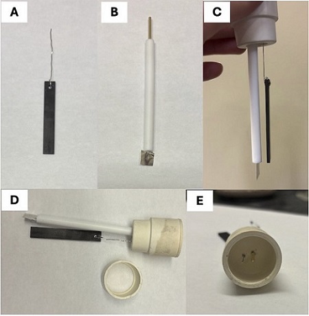
Figure 1: A. Assembly of the anode: Fabricated graphite electrode with Pt wire; B. Stony Lab Pt plate electrode; C. Septum with full electrode assembly; D. Electrode setup and the cut 24/40 septum lift; E. Top view of final electrode assembly (Photos provided by checking authors)
Fluorobenzene DABCOnium (bis)tetrafluoroborate (3). To a 50-mL round-bottomed flask was added a Teflon-coated rod-shaped magnetic stir bar (25.4×8 mm), 3.19 g (10.0 mmol, 1.0 equiv) Selectfluor II (1) by spatula and 1.88 mL (20 mmol, 2.00 equiv.) fluorobenzene (2) by 100-1000 μL micropipette (Notes 5,6,7). MeCN (45 mL, Note 8) was added to the flask using a 100-mL graduated cylinder (Figure 2B) (Note 9). Triethylamine (140 μL, 10 mol%, Note 10) was added to the flask with a 20-200 μL micropipette (Figure 2C). (Note 11). The flask was placed on a stir plate and secured by a clamp.
Figure 2: A. Assembly of electrodes; B. Appearance of reaction mixture before the addition of triethylamine; C. Color change observed immediately after the addition of triethylamine; D. Working and counter electrical terminals on Electrasyn 2.0 (Photos provided by checking authors)
The double-septa affixed with the reaction electrodes (Figure 2A) was placed on the top of the flask and secured with parafilm. The graphite electrode was connected to the working terminal (Figure 2D) of an IKA Electrasyn 2.0 using alligator clips (Figure 3A). The Pt electrode was connected to the counter terminal (Figure 2D) of the same Electrasyn using alligator clips. Stirring was turned on to 775 rpm at 25 °C (Note 12). The Electrasyn was programmed to run the reaction at a constant current of 3.5 mA for 1.5 F/mol for 10.00 mmol of substrate (Note 13).
Figure 3: A. Electrolysis in progress after 0.94 F/mol passed; B. Appearance of reaction in MeCN at the end of electrolysis (Photos provided by checking authors)
After electrolysis was completed (Figure 3B), the reaction mixture was vacuum filtered (measured 70 mbar) through ~2 cm of Celite in a 60 mL medium porosity fritted filter funnel. MeCN (3×10 mL) was used to wash the reaction flask and the Celite. The filtrate was transferred to a 500 mL round-bottomed flask (TS 24/40) (Figure 4A), and the volatiles were removed via a rotatory evaporator under reduced pressure (40 °C bath, 350 mbar to 50 mbar) (Figure 4B). The resulting tarry mixture was triturated with 50 mL of 1:1 Et2O:DCM until it formed a fine yellow or tan powder (Figure 4C, Note 14). The mixture was sonicated for 5 minutes and was allowed to settle. As much of the Et2O:DCM was decanted as possible using a Pasteur pipette. The remaining Et2O:DCM was removed by rotary evaporation under reduced pressure (40 °C bath, 350 mbar to 50 mbar). The solid residue was redissolved in the minimal amount of acetone (~110 mL, Notes 14, 15).
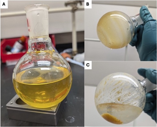
Figure 4. A. Acetonitrile crude solution after filtration; B. Crude material after removal of volatiles by rotary evaporation; C. Crude material during trituration. (Photos provided by submitting authors)
A Teflon-coated magnetic stir bar (25.4×8 mm) was added to the acetone solution. The HCl gas apparatus was then constructed. The gas generator consisted of a 100-mL three-necked round-bottomed flask (TS 24/40) filled with ~20 g dry CaCl2 (Figure 5B, Notes 16, 17). The middle neck was sealed with a greased stopper. The right neck was fitted with a pressure-equalizing addition funnel, filled with 12 M HCl (50 mL, Note 18). The left neck was sealed with a rubber septum (24/40) with a length of Teflon tubing inserted into the three-necked flask. The area around where the tubing pierced the septum was sealed using vacuum grease to minimize HCl gas escaping the flask. The other end of the Teflon tubing was inserted through another rubber septum (24/40). This second rubber septum was then pierced with a vent needle. The flask with the crude product/acetone solution was placed over a stir plate and stirred at 600 rpm. The septum with the vent needle and tubing to the HCl gas generator was affixed to the top of the round-bottom flask, and the tip of the tubing was immersed into the acetone (Figure 5A). Carefully, the 12 M HCl solution was allowed to drip (~10 mL every 3 minutes) onto the CaCl2 to generate HCl gas. HCl gas was bubbled through the acetone solution until precipitate stopped forming (Notes 19, 20). The septum was removed from the acetone flask which was momentarily set aside. The septum, stopper, and addition funnel were dismantled from the three-necked flask, and the addition funnel containing unused 12 M HCl was secured upright to one side by a clamp. The residual CaCl2/12 M HCl mixture in the flask was carefully diluted with water and neutralized with 4 M KOH aqueous solution (Note 21).
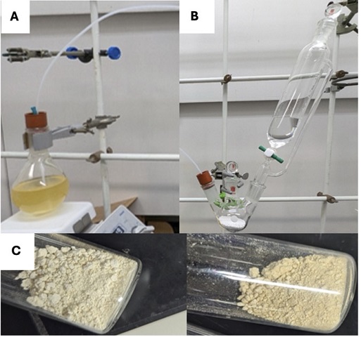
Figure 5. A. Product solution connected to the HCl gas generator; B. HCl generator; C. Product isolated in two independent runs (Photos provided by submitting authors)
The acetone/precipitate suspension was vacuum filtered (measured 70 mbar) through ~2 cm of Celite packed in a 60 mL medium porosity fritted funnel. The Celite and round-bottomed flask were washed with 2×10 mL of acetone. Et2O (~150 mL) was added to the acetone filtrate to precipitate the fluorobenzene DABCOnium salt (3). The DABCOnium salt 3 was collected in a 30 mL fine-porosity fritted funnel. Product 3 was washed with Et2O (3×10 mL). Air was pulled through DABCOnium salt 3 on the funnel for ~5 minutes, then the salt was transferred to a tared 20 mL vial and dried under vacuum (measured 300 mTorr). This yielded DABCOnium salt 3 as a light-yellow powder (2.01 g, 51%, Note 22). Compound 3 was found to be a mixture of regioisomers (86% para, 9% ortho, 5% meta by 19F NMR analysis) with 99.2 wt % purity by quantitative 1H NMR analysis using 1,3,5-trimethoxybenzene as an internal standard (Note 23).
2. Notes
1. Prior to performing each reaction, a thorough hazard analysis and risk assessment should be carried out with regard to each chemical substance and experimental operation on the scale planned and in the context of the laboratory where the procedures will be carried out. Guidelines for carrying out risk assessments and for analyzing the hazards associated with chemicals can be found in references such as Chapter 4 of "Prudent Practices in the Laboratory" (The National Academies Press, Washington, D.C., 2011; the full text can be accessed free of charge at
https://www.nap.edu/catalog/12654/prudent-practices-in-the-laboratory-handling-and-management-of-chemical. See also "Identifying and Evaluating Hazards in Research Laboratories" (American Chemical Society, 2015) which is available via the associated website "Hazard Assessment in Research Laboratories" at
https://www.acs.org/about/governance/committees/chemical-safety.html. In the case of this procedure, the risk assessment should include (but not necessarily be limited to) an evaluation of the potential hazards associated with
dichloromethane,
diethyl ether, and
hydrogen chloride gas, as well as the proper procedures for the generation and use of corrosive gases.
2. Platinum wire (99.95%, 0.020" d, P/N 4546) was purchased from Superpure Chemetals and used as received.
3. The submitting authors describe an alternative method for anode assembly in case a longer Pt wire is not available: A rubber septum (24/40) was pierced with an 18-gauge Cu wire, with 3.5 cm of wire exposed on the underside of the septum, and a NY-PT-Electrode-10x10-0.1 mm from Stony Lab (Pt plate 10×10×0.1 mm). A graphite electrode was fabricated by drilling a hole (3/32") in the top center of an IKA SK-50 graphite electrode, looping a 24-gauge Pt wire through the hole, over the top, then back through the hole, leaving 2.5 cm extra Pt wire at the top (Figure 1). A smartSpatula disposable plastic microspatula, trimmed to 3.5 cm length, was used to snugly secure the appended Pt wire and graphite electrode to the copper wire in the septum. Finally, a NY-PT-Electrode-10x10-0.1mm from Stony Lab (Pt plate 10×10×0.1 mm) was also used to pierce the septum (Figure 6)
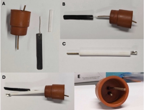
Figure 6: Alternative electrode assembly A. Materials for assembly of anode: septum with pierced copper wire, graphite electrode with Pt wire, trimmed microspatula to join the two together; B. Septum with full anode assembly; C. Stony Lab Pt plate electrode. D&E. Profile and top view of final electrode assembly. (Photos provided by submitting authors)
4. The exact amount of solvent used should be adjusted so as to immerse the electrodes. The entire Pt plate in the Stony Lab electrode should be submerged, with and without stirring on. The graphite electrode should be well submerged, but the solvent level should not touch the hole drilled into it, even under stirring. The reaction should not be significantly affected by a change in total solvent of ± 5 mL.
5. The submitting authors use a long necked 50-mL flat-bottomed flask that allows for a larger immersed surface area of electrode per amount of solvent used and prevents the stir bar from striking the electrodes. There is no secondary septum needed with this set up.
Figure 7. Electrolysis setup with a long necked 50-mL flat-bottomed flask (Photo provided by submitting authors)
6.
Selectfluor II (97%) and
fluorobenzene (98%) were purchased from Combi-Blocks and used as received.
7. Excess
fluorobenzene was used for efficient capture of the radical dication intermediate generated on the cathode. Less arene may be used, but the formation of over-reduced Selectfluor II (N-methyl DABCOnium) may become more significant.
8. Submitting authors used ACS grade
MeCN purchased from Fisher Scientific.
Acetonitrile was obtained by the checking authors from an inert solvent purification system (Solvent source:
Acetonitrile anhydrous, HPLC grade, Purchased from Caledon Laboratories Ltd.).
9. If a long necked 50-mL flat-bottomed flask is used, 70 mL of
MeCN is required for the reaction to have the electrodes sufficiently submerged.
10.
Triethylamine (>99%) was purchased from Sigma-Aldrich and used as received.
11. The reaction mixture will turn dark yellow or orange upon
triethylamine addition (Figure 2C), but that color fades within 30 minutes of stirring.
12. The stir rate used should be sufficiently high so that there are no permanently settled particles in the flask. The reaction will remain heterogeneous through its course. Efficient stirring is key to consuming as much
Selectfluor II as possible.
13. The run time for the electrolysis is more than 4 and a half days (approximately 112 hours). The reaction mixture will start being a slightly yellow color and gradually become deeper yellow as the electrolysis proceeds (Figure 3B). Suspended solids will remain at the end of the reaction.
1H NMR analysis of this solid in DMSO-d
6 revealed it to be primarily
N-methyl DABCO tetrafluoroborate salt. The reaction may be monitored for completion by
1H or
19F NMR spectrometry, looking for remaining
Selectfluor II in solution (
1H NMR: δ 4.70 ppm (q,
J = 7.5 Hz) or
19F NMR: δ 46.9 ppm (app. s) in CD
3CN, 298 K).
14.
Dichloromethane (stabilized with amylene, ACS reagent, ≥99.5%),
diethyl ether (Stabilized with BHT, ACS reagent, ≥99.0%) and
acetone (ACS reagent, ≥99.5%) were purchased from Sigma-Aldrich and used as received.
15. Some of the solid residue will not dissolve, so
acetone should be added until no further dissolution is observed.
16.
CaCl2 (anhydrous, pellets 4-20 Mesh) was purchased from Fisher and ground using a mortar and pestle before
17.
HCl is a corrosive and hazardous gas. Ensure the proper function of your fume hood before attempting this procedure. A new septum on the generator side is used for every run to ensure a good seal on the generator flask. Repeated use of the same septum results in a poor seal and
HCl gas leakage. For more details on
HCl gas generation used in this protocol, see:
J. Chem. Educ.
1995,
72, 1139.
18.
Hydrochloric acid (ACS reagent, 37 wt%) was purchased from Sigma-Aldrich and used as received.
19. The
HCl gas does not need to be dry, but it is important to deliver
HCl as a gas. Addition of aqueous
HCl to the
acetone solution would keep the
N-methyl DABCOnium byproduct in solution. The use of commercially available
HCl in organic solvents (e.g.
HCl in dioxane) risks precipitation of the desired product alongside the byproduct.
20. The purification should not require the use of all 50 mL of 12 M
HCl. To check if precipitate is still forming, turn off the stirring and allow the solids to settle to the bottom while
HCl bubbling is maintained. Excess 12 M
HCl should be carefully disposed of.
21.
KOH (ACS Reagent >85% pellets) was purchased from Sigma Aldrich and used as received.
22. Precise yields for two runs were 2.01 g (51%) and 1.97 g (50%), respectively. Characterization data for
3 (
para-isomer):
1H NMR
pdf (400 MHz, DMSO-
d6) δ 8.16 - 8.10 (m, 2H), 7.65 - 7.58 (m, 2H), 4.49 (t,
J = 7.5 Hz, 6H), 4.07 (t,
J = 7.5 Hz, 6H), 3.42 (s, 3H) ppm;
13C NMR
pdf (101 MHz, DMSO-
d6) δ 162.5 (d,
J = 249.9 Hz), 140.6 (d,
J = 3.1 Hz), 123.9 (d,
J = 9.4 Hz), 117.3 (d,
J = 23.4 Hz), 54.3, 52.8, 51.5 ppm;
19F NMR
pdf (376 MHz, DMSO-
d6) δ -109.85 (tt,
J = 8.7, 4.3 Hz), -148.10 (d,
J = 22.1 Hz) ppm. HRMS (ESI+): [M+] calc'd for C
13H
18FN
2: 221.1449, Found: 221.1451
23. Quantitative
1H NMR
pdf analysis was performed by dissolving 35.6 mg of
DABCOnium product
3 and 14.0 mg
1,3,5-trimethoxybenzene (99.8%, Standard for quantitative NMR, TraceCERT was purchased from Sigma-Aldrich and used as received.) in a minimal amount of DMSO-d
6 (~0.8 mL). A drop of D
2O was added to the NMR sample to ensure the product was fully dissolved. The resulting solution was transferred to an NMR tube and a 16 scan
1H NMR with 30 s relaxation time was performed. The qNMR showed the
para-isomer to be 85.5% of the product by mass, with a purity of 99.2% when the minor isomers are considered. The selectivity of the amination reaction is
m: o: p= 1.0: 1.9: 18.0 as found by
19F NMR.
Working with Hazardous Chemicals
The procedures in
Organic Syntheses are intended for use only by persons with proper training in experimental organic chemistry. All hazardous materials should be handled using the standard procedures for work with chemicals described in references such as "Prudent Practices in the Laboratory" (The National Academies Press, Washington, D.C., 2011; the full text can be accessed free of charge at
http://www.nap.edu/catalog.php?record_id=12654). All chemical waste should be disposed of in accordance with local regulations. For general guidelines for the management of chemical waste, see Chapter 8 of Prudent Practices.
In some articles in Organic Syntheses, chemical-specific hazards are highlighted in red "Caution Notes" within a procedure. It is important to recognize that the absence of a caution note does not imply that no significant hazards are associated with the chemicals involved in that procedure. Prior to performing a reaction, a thorough risk assessment should be carried out that includes a review of the potential hazards associated with each chemical and experimental operation on the scale that is planned for the procedure. Guidelines for carrying out a risk assessment and for analyzing the hazards associated with chemicals can be found in Chapter 4 of Prudent Practices.
The procedures described in Organic Syntheses are provided as published and are conducted at one's own risk. Organic Syntheses, Inc., its Editors, and its Board of Directors do not warrant or guarantee the safety of individuals using these procedures and hereby disclaim any liability for any injuries or damages claimed to have resulted from or related in any way to the procedures herein.
3. Discussion
Radical aromatic C-H amination has been an active area of research in reaction method development for the last decade, due to the prominence of aryl amines in pharmaceutical compounds.
3,4,5,6,7,8 Arene oxidation methods were extensively explored and prized for their use of diverse nitrogen sources.
9,10,11,12,13,14,15,16,17,18,19,20,21 However, workable arene scaffolds are limited, due to the difficulty of direct oxidation of arenes that are not electron-rich. Electrophilic nitrogen radical methods have been developed in parallel, with selectivity and arene scope generality dependent on the nature of the generated radical.
22,23,24,25,26,27,28,29,30,31,32,33,34,35,36,37,38 Increasing size and electrophilicity of the radical both correlate with increased amination selectivity.
7,24 Because of this, the
N-Me DABCOnium radical dication, among the bulkiest and most electrophilic
N-radicals, has been investigated for selective C-H amination, showing a broad arene scope of selective amination.
24,39,40 Figure 8 summarizes the arene scope of the methodology.
39 This method can functionalize various arenes including electron-rich and neutral arenes, as well many heterocycles. In most cases, one regioisomer is observed, and for some substrates high regioselectivity (>32:1 to 5:1) can be observed. High selectivity is explained by a transition-state with significant charge-transfer character, inducing selectivity for the most nucleophilic position in the arene.
7,24 The aryl DABCOnium salts can be isolated or readily converted to aryl piperazines. Since the aryl DABCOnium is a quaternized salt, their diversification has been explored, yielding procedures for 2-step C-H methylation, phosphorylation, arylation, and borylation.
39,40,41 This broad diversity makes large-scale, metal-free synthesis of DABCOnium salts highly desirable.
Figure 8. Selected arene scope of the electrochemical C-H amination
In the mechanism of this reaction (Figure 9),
N-Me DABCOnium radical dications (I) are produced at the cathode by reduction of SelectFluor II and fluoride extrusion. In the presence of an arene, a radical cation-pi interaction is proposed which is investigated preliminarily using DFT calculations and cyclic voltammetry analysis.
39 Radical addition to the arene yields a radical addition intermediate (II), which is then oxidized (presumably at the anode) to form III and deprotonated to yield the aryl DABCOnium salt
3. Previously, larger scale synthesis of pure aryl DABCOnium salts was challenging due to the formation of significant amounts of
N-methyl DABCOnium BF
4 as a contaminant which was difficult to separate. The described method pushes the achievable scale well into the gram scale, a five-fold scale increase over the previously described procedure, utilizing a reliable and known method for HCl gas generation safe enough to be employed by undergraduates.
42 With this method, the further diversification of aryl DABCOnium salts can be more easily explored.
Figure 9. Proposed mechanism for electrochemical arene C-H amination with Selectfluor
Appendix
Chemical Abstracts Nomenclature (Registry Number)
SelectFluor II: 1-Fluoro-4-methyl-1,4-diazabicyclo[2.2.2]octane-1,4-diium di(tetrafluoroborate); (1) (159269-48-4)
Fluorobenzene; (462-06-6)
Triethylamine; (121-44-8)
CaCl2: Calcium chloride; (10043-52-4)
HCl: Hydrochloric acid; (7647-01-0)

|
Griffin Stewart is from Hattiesburg, Mississippi. He received his B.S. in chemistry from the Georgia Institute of Technology in 2021. Griffin is currently a Ph.D. candidate in the Malapit Lab at Northwestern University and a recipient of the US National Science Foundation Graduate Research Fellowship. His research focuses on synthetic organic electrochemistry for the C-H functionalization of arenes via electrophilic heteroatom radicals. |

|
Christian Malapit is a synthetic organic chemist from the Philippines. He earned his Ph.D. in Chemistry at the University of Connecticut under the mentorship of Prof. Amy Howell, followed by postdoctoral training with Prof. Melanie Sanford at the University of Michigan. As an NIH Pathway to Independence Fellow, he conducted research in synthetic organic electrochemistry in collaboration with Profs. Shelley Minteer and Matthew Sigman at the University of Utah and the NSF Center for Synthetic Organic Electrochemistry. Christian is currently an Assistant Professor of Chemistry at Northwestern University, where his research group focuses on synthetic electrochemistry and the development of next-generation organic materials for redox flow batteries. |

|
Negin Nabavi received her B.Sc. in 2022 in Chemistry from Concordia University in Montreal where she worked under the supervision of Prof. Pat Forgione. She then moved to Toronto to work at Axios Research. Negin is currently a 2nd year Ph.D. student in the lab of Prof. Sophie Rousseaux at the University of Toronto. Her research is focused on methodology development and mechanistic studies of nickel-catalyzed transnitrilation reactions. |

|
Sophie Rousseaux is an Associate Professor of Chemistry at the University of Toronto, where she also holds a Canada Research Chair (Tier 2) in Organic Chemistry and serves on the Scientific Leadership Team of the Acceleration Consortium. Her group's research interests include organic synthesis, catalysis, and organometallic chemistry, with a particular focus on the synthesis of small rings and nitrile-containing molecules. |
Copyright © 1921-, Organic Syntheses, Inc. All Rights Reserved